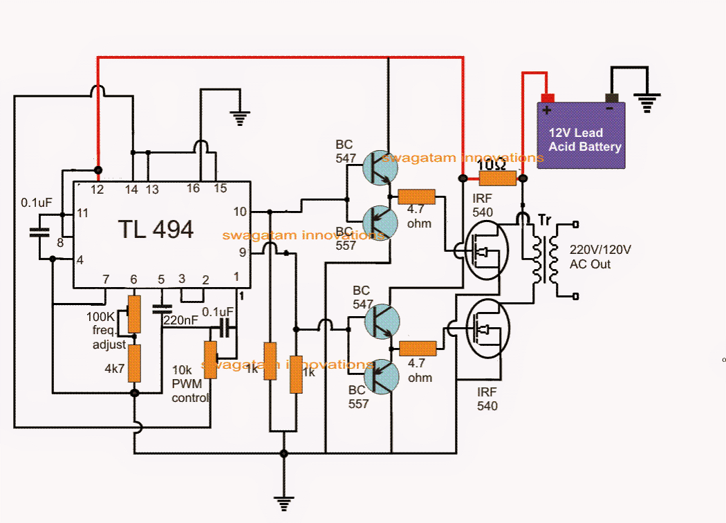
Single Phase Pwm Inverter Circuit Diagram
Inverter diagram circuit pwm watt Inverter phase pwm circuit six diagram Inverter ti 3phase inverters
Sukam Inverter Circuit Diagram Download | Home Wiring Diagram
Power circuit of the single-phase three-wire inverter system Three-phase voltage source pwm inverter the circuit model of a typical Single phase pwm inverter
Sukam inverter circuit diagram download
Power circuit of the single-phase three-wire inverter system12+ 3 phase inverter circuit diagram Rc-controlled single-phase pwm inverter.Phase inverter.
Inverter pwm controlling lossesInverter multilevel pwm Inverter circuit diagram sine wave board arduino electronics schematic power solar projects 50hz sukam inverters wiring using ic charger simpleInverter 5000 watt pwm circuit diagram.

Inverter phase circuit three make generator pwm circuits diagram homemade single simple projects electronic wave driver explained wiring solar mosfet
3 phase inverter wiring diagramExample of the basic operation of the single phase pwm dc-ac inverter Inverter pwm circuit phase power system three rectifierInverter pwm.
Designing and controlling a power inverter (dc to ac)3-phase pwm power inverter circuit Inverter pwm phase controlledInverter arduino.

Pwm inverters inverter diagram block circuit introduction circuits pulse width modulation electronic gr next diagrams based elementary using
Arduino three phase inverter codeInverter circuit pwm tl494 ic sine wave modified pinout using circuits application makingcircuits ne555 inspirasi simplest functions above looking many Introduction to pwm inverters.How a 3 phase pulse width modulation (pwm) vfd inverter works.
Inverter voltagePower circuit of the proposed single-phase pwm multilevel inverter Ic tl494 pwm modified sine wave inverter circuitPhase inverter circuit three driver bridge circuits diagram mosfet line tweet half rail ics make.

Figure 1 from the use of harmonic distortion to increase the output
Inverter pwm phaseInverter scheme Inverter pwm modulation1 block diagram of single phase inverter.
Pwm inverter phase figure three voltage harmonic distortion increase use outputInverter pwm Schematic diagram of a single-phase voltage source inverterThree phase inverter circuit.

Phase inverter
Make this 3 phase inverter circuit ~ electronic circuit projectsThe single-phase inverter scheme .
.

Arduino three phase inverter code | Electro Bhai | - YouTube

How a 3 Phase Pulse Width Modulation (PWM) VFD Inverter Works

12+ 3 Phase Inverter Circuit Diagram | Robhosking Diagram

Make this 3 Phase Inverter Circuit ~ Electronic Circuit Projects

RC-controlled single-phase PWM inverter. | Download Scientific Diagram

Power circuit of the single-phase three-wire inverter system

IC TL494 PWM Modified Sine Wave Inverter Circuit