Relay Board Circuit Diagram
2 channel relay board Simple relay circuit and pcb Basic relay circuit
schematics - How to keep the state of relay - Electrical Engineering
4 channel relay board Relay 230v capacitor ldr Relay pcb fzz fritzing
Schematic diagram relay driver board project
Relay board diagram arduino schematic control fan channel shield wiring channels above complete clickHow to build a control circuit with adjustable working time via wi-fi Relay breadboardRelay diagram wiring use pole single double.
How to make your own relay moduleSimple relay circuit and pcb Relay songle relais schaltplan 5v arduino module mikrocontroller projektElectronics repair made easy: relay found in switch mode power supply.

Frage zu 5v-relais
8 channel lpt relay boardRelay diagram circuit wiring el817 5-relay module circuit diagram and pcbRelay diagram wiring simple pole switch 12v wire volt circuit electrical diagrams cube ice lights dsmtuners prong mini ly2 omron.
Single relay boardRelay layout Board relay drawing8-channel relay board.

Relay module make schem
Simple 4 pin relay diagramRelay normally diagram closed open circuit schematic momentary 5 pin relay wiring diagramRelay board single 12v diagram diy circuit researchdesignlab.
Relay module circuit diagram pcbRelay schematic circuit output electronic Normally closed relay diagramRelay pcb board electronic project.

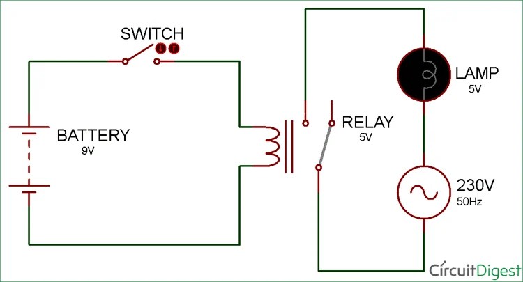
Relay circuit
Circuit relay simple board diy diagram led nc connectedRelay breakout schematic circuit board pcb Relay circuit and breakout boardMbed: diy simple relay circuit board.
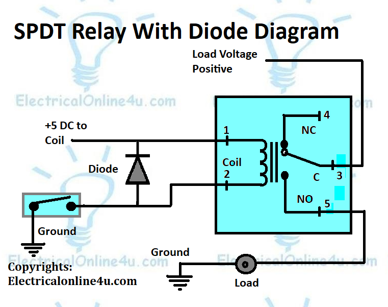
Schematic diagram relay driver board projectRelay control using simple arduino circuit switch power datasheet lock magnetic turn pc supply parameters 12v 5v plug ac 230v Relay use diagram wiring coil diode voltage pole single throughRelay arduino circuit board shield ethernet automation uno diagram project control using module schematic 5v channel 3v opto isolated gpio.

Relay arduino module close diagram channel circuit drive takes time board opto esp8266 isolated port electrical pins connect info schematic
Relay channel schematic board circuit arduino topic electronics lab pcb connection control output4-channel relay driver circuit and pcb design Safely connecting a relay board to external power supplySchematic 220v relay relays arduino board problem using mention forgot drive had stack.
Electronic project: relay board pcbPcb relay Relay relays uno inputs outputs module l298 mega shown bridge examples any using these5 pin relay wiring diagram.

230v relay wiring diagram
Relay schematic keep state circuit circuitlab created usingFinal year project 2013/2014: week 3 of fyp 2 Pcb relay trying to figure how to wire it...On the drawing board: relay board.
Lpt powerRelay diagram board breakout circuit setting Relay circuit channel driver pcb module diagram board 5v arduino 12v circuits project relays ac choose circuitdigest.

5 Pin Relay Wiring Diagram - Use Of Relay

Simple Relay Circuit and PCB
230v relay wiring diagram - Wiring Diagram and Schematic Role

arduino - Problem using Relays at 220V with 595 - Electrical

SCHEMATIC DIAGRAM Relay Driver Board Project

Basic Relay Circuit - 01 - YouTube