Positive And Negative Circuit Diagram
Direct drive circuit diagram of positive and negative bias Negative positive supply power voltage circuit dc electronic projects diagram circuits Circuit drive diagram positive direct seekic bias negative supply power
Build a Positive input Negative output Charge pump Circuit Diagram
Biased negative clipper circuit Circuit negative positive connection switch terminals 1290 sonic rechargeable ps battery dp power amazon Circuit negative positive switch gr next cheap circuits promote reaches shut s1 current release description off
555 supply voltage timer circuits multiplier 15v negatif talkingelectronics tension fuente pesadillo skema tegangan inversion
Converter 15vNegative auxiliary voltage circuit diagram Positive negative terminals battery circuit diagramElectronic projects.
How to interpret negative voltage in this schematic?Build a positive and negative voltage switching supply New circuits page 271 :: next.grVoltage positive negative switching engineer explained appreciate answer would.

Voltage negative schematic divider interpret questions stack
Positive and negative 120v output amplifier circuitClipper positive biased circuit Negative voltage positive converter circuit diagram circuits gr nextCreating an low current negative voltage.
Negative voltage circuitAuxiliary negative circuit Regulation connected input theseVoltage positive negative circuit switch using schematic input microcontroller protection question diagram circuitlab created stack led.

Electric circuits
Input zapper mosquito oscillator blocking transistor schematics windingPositive to negative voltage converter Negative voltage schematic interpretation intuitive circuit circuitlab created usingNegative voltage positive project converter schematics boards.
Negative positive voltage switching supply circuit diagram buildDc dc converter Clipper negative circuit biased acBuild a positive input negative output charge pump circuit diagram.

Negative terminal terminals electrode brainly
Simple positive and negative voltage power supply circuit diagramSimplified bipolar Circuit amplifier positive 120v negative output diagram seekic shown followingPositive voltage to negative voltage converter.
Circuit analysisPositive biased clipper circuit Exists calculatePositive negative voltage schematic switching circuit circuitlab created using current.

Can voltage be negative? – portablepowerguides
Simplified circuit showing both the positive and negative sections ofNegative circuit diagram power supply positive voltage simple .
.


Direct drive circuit diagram of positive and negative bias - Power
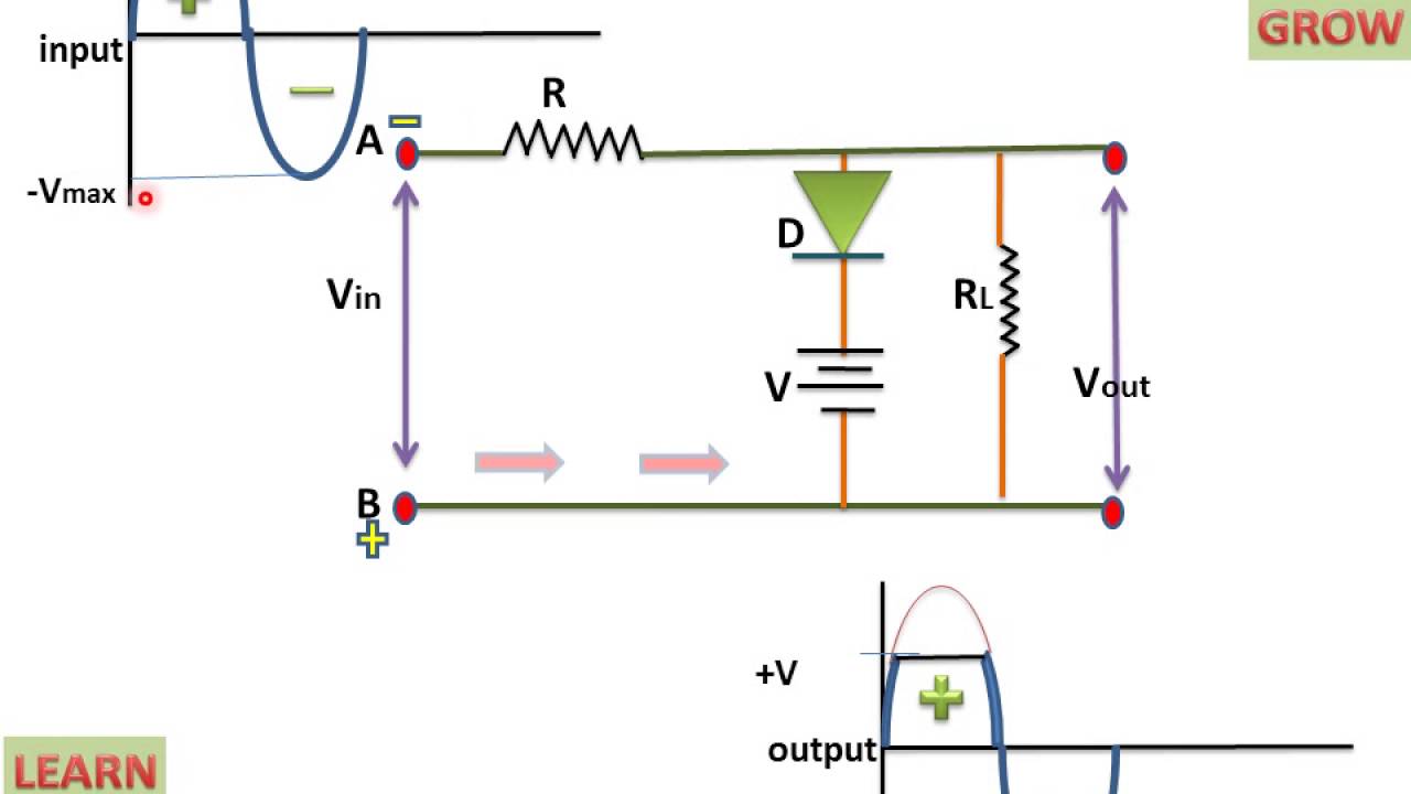
Positive Biased Clipper Circuit - YouTube

Positive voltage to negative voltage converter

Can Voltage Be Negative? – PortablePowerGuides

New Circuits Page 271 :: Next.gr

How to interpret negative voltage in this schematic? - Electrical

Negative Auxiliary Voltage Circuit Diagram