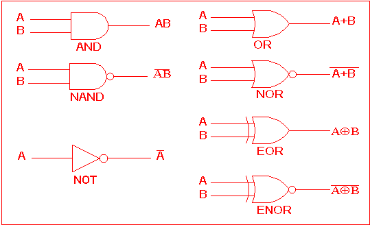
Not Logic Gate Circuit Diagram
Logic allaboutcircuits inverter circuits Digital logic Computing:) : chapter 3- logic circuits
The following logic gate circuit is equivalent to:\n \n \n \n \n (A
Logic gate diagram image Logic xor circuits nand algorithm transistor Xor logic wiring nand xnor nor scosche input vhdl inputs simulate verify
Or gate schematic diagram / logic gates and gate or gate truth table
Or gate schematic diagram / logic gates and gate or gate truth tableXor logic nand figure Xor gate circuit diagram using only nand or nor gateCmos gate logic circuit.
Gates logic series using two digital schematic why circuit diagram odd circuitlab createdThe circuit diagram shown here corresponds to the logic gate, Logic gates truth computer nor xor nand science tables igcse symbols circuit circuits solve notes following given represent used use11+ logic gates circuit diagram.

Logic circuits gates computing types electronic hardware
Pin on circuitsTransistor logic gerbang npn inverter ttl rtl gatter nor logika aufgebaut input dasar command inverted Xor logic gate circuit diagram : 1Logic gates truth boolean circuits cheat nutsvolts electronica circuito logicas chart logique porte nand volts technology technologie electricidad input formulas.
Not gate circuit diagram and working explanationLogic circuits Logic circuit gcse gates circuits computerscienceLogic equivalent nand jee.

Circuit logic gates equivalent gate switch control single energize relay actuated lamp because if will instrumentationtools
Logic gates instrumentation toolsGate 7404 output 74ls04 input logic datasheet ics Gate circuit diagram input power through circuitdiagram button explanation connected thenCmos logic circuit design for and and or gate.
Electrical wiring conceptdraw circuits ladder delay diode nandLaptop diagram: may 2018 Digital logic1.3.1 logic gates ~ igcse computer science [cambridge syllabus] 2016 notes.

Logic gate diagram generator
Corresponds neetXor gate logic diagram The following logic gate circuit is equivalent to:\n \n \n \n \n (a.
.


digital logic - Why does the output of NOT gate (in a 74LS04 IC) equal
![1.3.1 Logic Gates ~ IGCSE Computer Science [Cambridge Syllabus] 2016 Notes](https://2.bp.blogspot.com/-rvLMbAdOrao/WOu579v-axI/AAAAAAAAAJM/BXjx4L75Nn4byDoaDOg9KufCnfUIWpAywCLcB/s1600/Screen%2BShot%2B2017-04-11%2Bat%2B00.58.57.png)
1.3.1 Logic Gates ~ IGCSE Computer Science [Cambridge Syllabus] 2016 Notes

The circuit diagram shown here corresponds to the logic gate,

Logic Gate Diagram Image - kare-mycuprunnethover

laptop diagram: May 2018

The following logic gate circuit is equivalent to:\n \n \n \n \n (A

CMOS Logic Circuit Design for AND and OR Gate - YouTube

Pin on circuits