4 Bit Full Adder Schematic
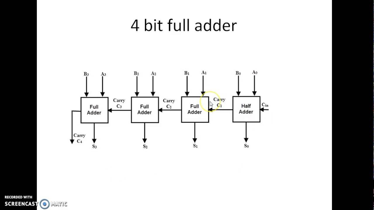
Combinational and sequential design of a 4-bit adder. (a) ha circuit Adder bit nand using gates input two gate circuit only [diagram] logic diagram of 4 bit full adder full version hd quality
Glossary of Electronic and Engineering Terms, IC Adder Chip
4-bit full adder using two-input nand gates ~ techno central 8 bit full adder Adder circuit diagram schematic bit works figure
Adder subtractor bit circuit add sub overflow complement logic detection carry designing control zero addition line questions digital computer
Circuit adder bit diagram logic computing learn letFull adder logic diagram Adder adders libretexts circuits pageindexCd4008 4-bit full adder ic pinout, working, example and datasheet.
Adder circuit diagram geeksforgeeks bit subtractor binary source16 bit full adder digital circuit simulation using logisim software Digital logicAdder logic wiring calculators.

Adder ripple binary parallel
Full-adder circuit, the schematic diagram and how it works – deeptronicCs 3410 fall 2016 lab 1 Adder bitAdder circuit construction binary circuits qiskit sourav gupta.
Adder bit description introduction hardware language half ppt powerpoint presentation gate input level slideserve10+ adder circuit diagram 2 bit full adderAdder half adders.

Adder bit logisim using circuit cs build labs cornell lab1 courses edu create re ta sub ask
Adder circuit combinational ha sequentialSerial adder bit subtractor parallel module load schematics used 4-bit serial adder/subtractor with parallel load – altynbek isabekov5 logic circuits.
4 bit adder circuit diagram, 4, free engine image for user manual downloadGlossary of electronic and engineering terms, ic adder chip Full adder circuit: theory, truth table & constructionAdder bit logic four circuits figure x64 sonoma cs bob edu.

Let's learn computing: 4 bit adder circuit
Adder ic chip bit circuit circuits chips schematic binary four ttl carry numbers gr next repository6.4: 2-bit adder circuit Adder logisimAdder carry circuit bit ahead look diagram ripple cla truth table.
.


PPT - Hardware Description Language - Introduction PowerPoint

Full Adder Logic Diagram - General Wiring Diagram

4 Bit Adder Circuit Diagram, 4, Free Engine Image For User Manual Download

6.4: 2-Bit Adder Circuit - Engineering LibreTexts

Combinational and sequential design of a 4-bit Adder. (a) HA circuit

2 BIT Full Adder | Mixed Electronics
8 bit full adder - YouTube

Full-Adder Circuit, The Schematic Diagram and How It Works – Deeptronic